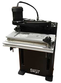
Usage of 3D printer SkyOne as a 3D milling machine
This guide contains the step-by-step tutorial about usage of 3D printer SkyOne for 3-dimensional and artistic milling through the use of software BlenderCam.
It is needed for work:
- 3D printer SkyOne with installed engraving and milling set (cutter head and aluminum base).
- Software BlenderCAM (open source project, available for free downloading and use:
- Software Repetier Host (open source project, available for free downloading and use: )
It could be usefull for work:
- Software Blender – it is needed just in case, if the milling will be implemented according bitmap image. BlenderCAM also can be used, but user interface of BlenderCAM differs significantly from Blender. So preparing of a virtual model in Blender is more suitable, than in BlenderCAM. (Blender is an open source project, available for free downloading and use: ).
- BlenderCAM manual
- Blender manual
- Guide-book "Blender Basics" - 4th edition:
3D milling according available 3D model
BenderCam allows to prepare of a G-code file which is suitable for milling using 3D printer SkyOne.
It is needed to have a 3D model, which is acceptable for 3D milling. Considering special aspects of a working piece (a cutter tool), there is a limitation for such 3D models: it is impossible to mill a form with any overhanging parts (including any cavities or hollows inside an enclosed volume).
A suitable for milling 3D model should be loaded in BlenderCAM. The native file extension of Blender - blend. The rest file extensions can be opened via import menu: File > Import (file extension). Choose the location and file of the importing model and press the button "Import".
In this example the model is in STL format. In order to import STL model in BlenderCAM, it is needed to turn on a special add-on. For this open menu File > User preferences.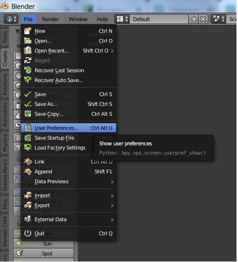
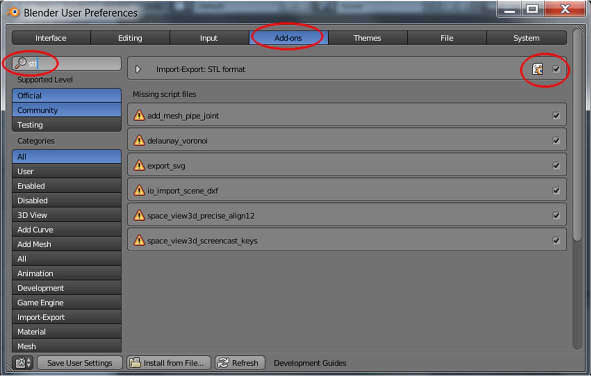
Choose Add-ons tab in the opened window, type in "stl" into the search bar and then place a check mark "Import-Export: STL format". Save the settings. Now it is possible to import STL format models in BlenderCAM.
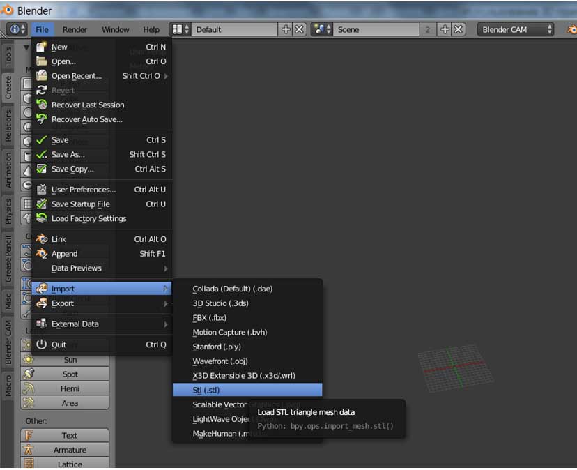
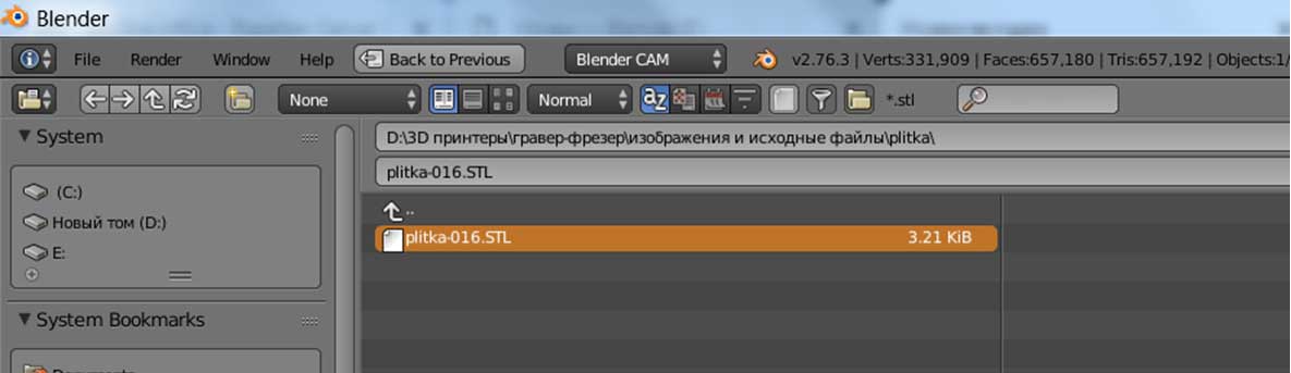
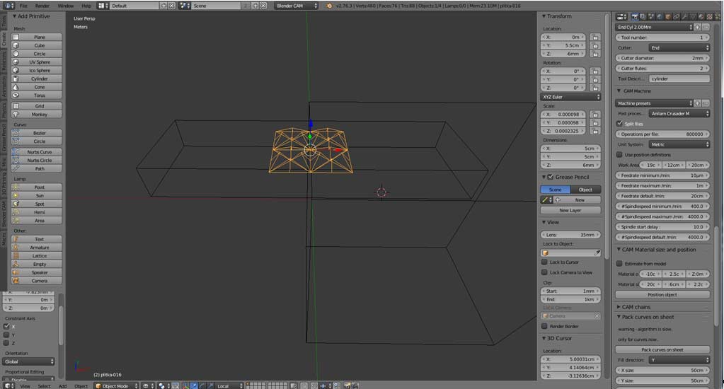
To import the model choose menu File > Import >Stl (*.stl). In the opened window locate and choose the model file and press the button "Import STL". In this example 3D milling of an ornamental tablet will be implemented.
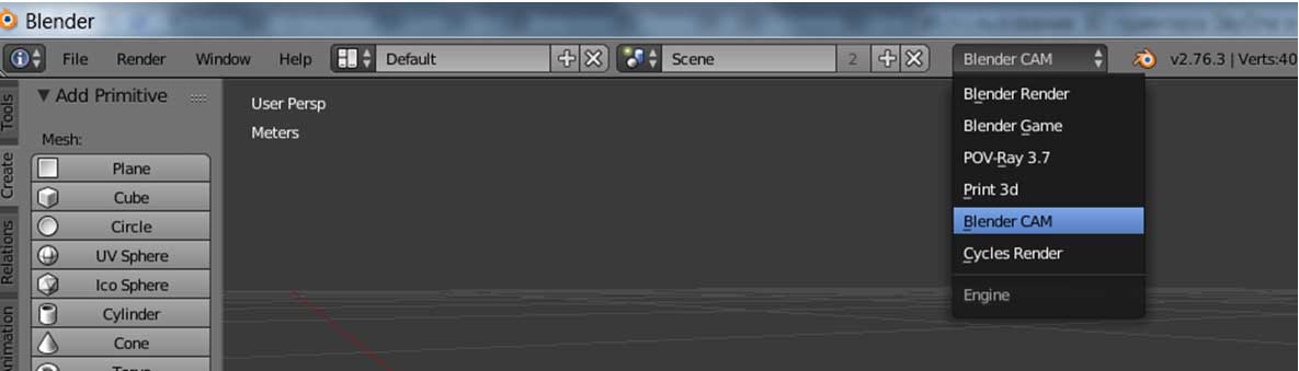
Check that the program is in Blender CAM mode (drop-down menu in the top part of the program window). Unles it is not so, shoose Blender CAM from the list.
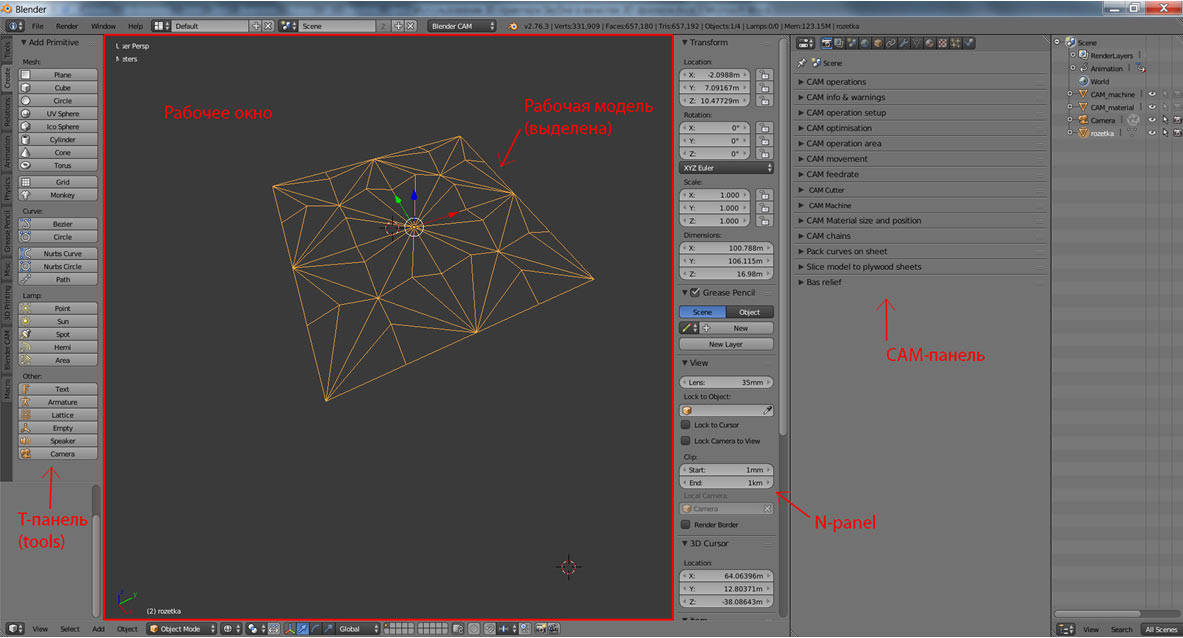
In the BlenderCAM software a mouse wheel is used for scaling. To rotate and move an object it is needed to press and hold the wheel and move the mouse. All operations should be done in the work window above the model. When the mouse pointer is located above an instrument panel or other parts of interface, the mouse buttons and wheel have another role.
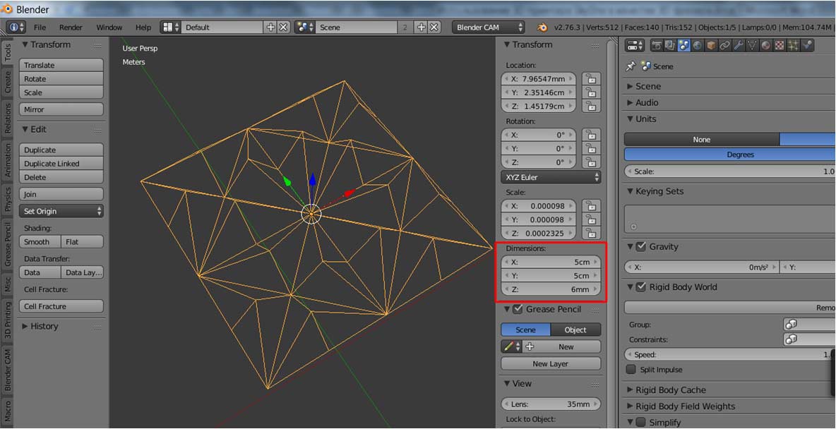
The imported 3D model either has indefinite size or unsuitable for milling size. Firstly it is needed to set the system of units - metric in this example. To do that shoose the tab "Scene" (the button with threedimensional forms image). In the "Units" section select "Metric" units of measure.
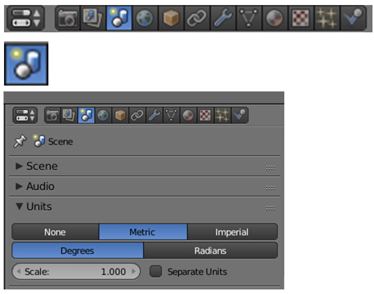
In the tol left side of the work window "Meters" note will be displayed.
Next select the model in the work window by right mouse click (if it is not selected yet and showed in black color).
Set suitable size for the selected model - this size should conform the ready milled object. To set the size set corresponded dimensions for axises x, y and z at the Т-panel (in "Dimensions" section).
The scale (relative to the original size) is shown in the "Scale" section. To maintain the original aspect ratio in XY plane, set the equal scale ratio for X and Y axises (corresponded dimension will be changed automatically).
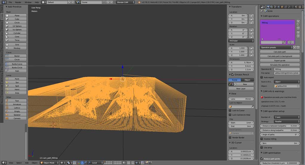
Then open tab Renders to display CAM panel and "CAM operations" section.
Section "CAM operations"
Press "+" in this section to add a new CAM operation for the model. The first operation will be automatically named Operation_1. This name can be changed for any another meaningful one - set new name in the field "Operation name".
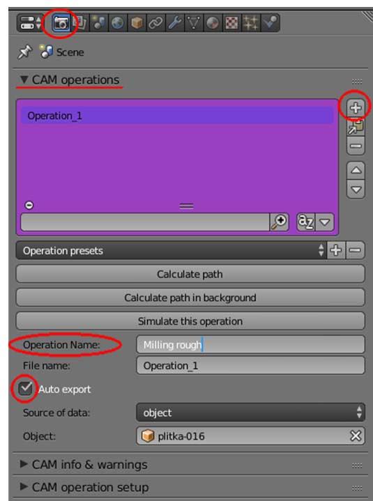
In the "CAM operations section" the option "Auto export" default is checked. When it is checked, the g-code is generated and saved to file automatically after calculation of the tool path (after pressing of the button "Calculate path", with the file name which is set in the field "File name"). If this option is not checked, the g-code file is generated just after pressing the button "Export gcode". This button becomes available just after successfull tool path calculation.
Object - determines the model, which is base for the path calculation.
Section "Cam info & warnings"
Potential problems and some support information according the calculated tool path are shown in the section "Cam info & warnings". It is recommended to expand this section in order to see the tool path calculation result.
Section "CAM operation setup"
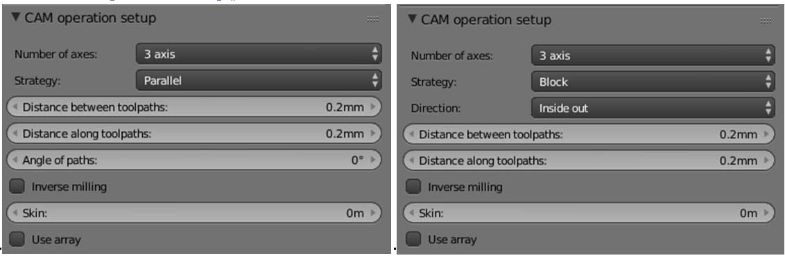
Basic settings of the CAM operation is determined in the section "CAM operation setup".
Number of axis – 3 axis (the 3D printer SkyOne has 3 axises of displacement).Strategy – CAM operation strategy. This strategy is used for tool path calculation. The best suitable strategy depends on the model. More detailed information about strategies is available in the BlenderCAM manual. Below are the most popular strategies:
- Parallel — a tool executes parallel movements at a selected angle.
- Profile(Cutout) — cut out a silhouette through the use of displacement option.
- Drill — determines circles or squares on any 2D-curve, and converts them into drilling operations.
- Cross — tool path is executed on intersect trajectories.
- Block — the tool executes operation by blocks.
- Spiral и Circles — tool path along circles or spirals, it is more suitable for round oblects.
Settings fields are defferent for different strategies.
For this example strategies parallel or block could be selected. In this guide parallel strategy will be used.
Distance between toolpaths - it is a displacement between two neighboring toll passages. The value depends on several points::
- work material (the harder material - the less material can be cut in one pass);
- feedrate during cutting operation (the higher cutting speed - the less value should be set);
- diameter and strength of a cutter tool (the thiner cutter and the less diameter - the less value should be set);
- maximum cutting depth (the deeper cutting - the less value);
- desired quality and detailed elaboration of the model (the less value - the higher quality and more detailed object could be processed).
The less is set value, the more time the process takes.
For this example (work piece from a wood, cylinder cutter diameter 2 mm, cutting depth is 6 mm) the value will be set 0.2 mm.
Distance along toolpaths – the operation path density, it could have an impact on accuracy. For the in hand example it is 0.2 mm.
Angle of paths – angle of processing paths. For the example it is 0°.
Skin – a layer of the material for the next operation. It is convinient for rough and finishing cut. For this example it is 0.
Inverse milling – it is used for making of a form for the oblect. This option ss not checked for the example.
Direction – path direction for block and spiral strategies - inside out or outside in.
Section "CAM optimization"
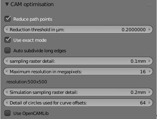
Reduce path points — decreasing of points number along the tool path, decreases the quantity of commands for the operation. The ready G-code becomes shorter, the operation time decreases. This option is checked for this example.
Reduction threshold in µm – reducing of a short distance points (шт micrometerы) along the tool path.
Use exact mode — exact mode suitable for full 3D strategies: parallel, cross, block, spiral, circles, waterline, outlinefill, carve. Not exact mode is used for high polygonal meshes. The exact mode is used for the example.
Section "CAM operation area"
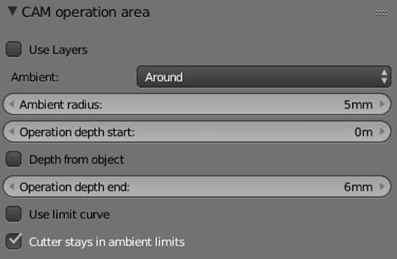
Use layers - set layers for rough cut. It is not checked for the example.
Ambient – the area around the model to be cut. It could be either All - all material will be cut (work piece size is set in the section "CAM material size and position"), or Around – the set value of material around the model will be cut. This value is determined in the field "Ambient radius". For this example it is set as 5 mm around the model (Ambient: Around, Ambient radius: 5mm).
Operation depth start – z axis coordinate, which is considered as cutting start. For the example it is =0. (From the zero position downward).
To execute cutting all the depth of the model, it is necessary to set correct value of the model location along z axis on the N-panel. If the parameter "Operation depth start" is set as 0 and cutting should be done all the model height, it is necesary to set z-coordinate of the model location (Location: Z) equal to the model height, but negative sign.
The cutting depth could be calculated from the model dimensions (so check the option "Depth from object"), or could be set manually in the field "Operation depth end" (6 mm for the example).
Section "CAM movement"
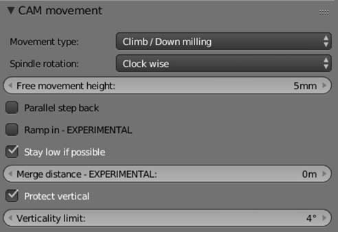
Movement type — the type of moovement of the cutter inside the material. For milling using 3D printer SkyOne it is possible to set Climb/Down Milling.
Spindle rotation — spindle rotation direction - this parameters is not imported in g-code, but it is used for tool path calculation. If the spindle rotates CCW, all operations should be execute in the opposite direction. Set this parameter Clock wise.
Free movement height — it is the height of tool traveling between paths. The more this value - the higher tool position during no load movements - the more timee the operation takes. Set the value 5 mm for the example.
Parallel step back – not checked for the example.
Ramp in – not checked for the example.
Say low if possible – checked for the example.
Protect vertical – checked for the example.
Field verticality limit - is set 4° for the example.
Section "CAM feederate"
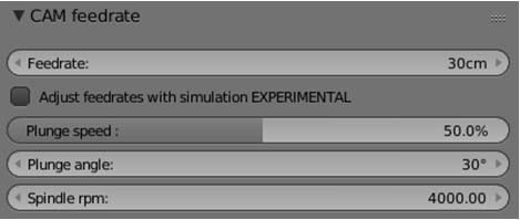
Feedrate - the machine path per minute, it is set as 30 cm for this example.
Spindle rpm — spindle rotation speed, rpm. It is 4000 rpm for SkyOne 3D printer.
Section "CAM Cutter"
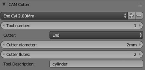
Section 'CAM cutter' contains the cutter parameters. It is possible to select a ready type in the dropdown list "Cutter presets" or set cutter parameters manually. For this example it is choosed end cylinder cutter 2 mm diameter. Parameters of this cutter is automatically displayed in fields below.
Cutter – cutter tool type – "end" for this example.
Cutter diameter – tool diameter – 2 mm for this example.
Cutter flutes – 2 for the example.
Tool description – the name, it is possible to set any meaningful name.
Section "CAM machine"
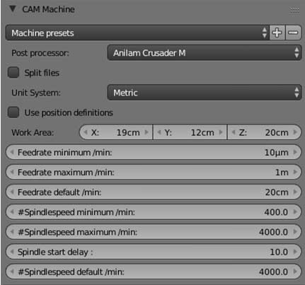
Section "CAM machine" contains machine parameters, so it is necessary to set here values, which conform to real dimensions of the 3D printer SkyOne. These parameters are used for tool path calculation.
Important parameter - post processor - this postprocessor is used for g-code generation (which forms into an output file). To use 3D printer SkyOne with software Repetier-Host, the setting Anilam Crusader M is suitable. Other settings are not tested with SkyOne 3D printer.
Unit system – system of units of measurements – metric for this example..
Work area – should be set if option Use position definitions is not checked. In case if the model operation requires more space, than the work area allows, a warning is displayed, and g-code can be generated not completely, incorrectly or even not generated at all. Work area in XY plane is 190x120 mm. The maximum displacement along the Z axis depends on the material piece height. f
Split files – this parameter limits the maximum size of an output file. If this option is checked, the maximum number of operations for one file should be set in the field operations per file. Our example is a simple 3D model and doesn't require a large number of operations, so this option is not checked for this example.
Feedrate minimum/maximum — minimum and maximum feed speed. These parameters limit the speed selection at the feedrate panel. Set the maximum feedrate for the 3D printer SkyOne - 1 m/min.
Feedrate default – the value of this parameters depends on many factors, such as a cutter diameter, material hardness, layer height (which will be cut through one pass and set in the field Distance between toolpaths in the section "CAM operation setup"). As in this example the ready g-code performs the first operation - pass through and cut the material equal to the cutter diameter, the default feedrate should be limited. For this example it is equal to 20 cm/min. During real operation it is recommended to reduce the feedrate additionally to 25-30% in the Repetier-Host software. For the for further work the feedrate can be set 100% or even more. Feedrate default is set 20 cm/min as the first pass goes through the material and cut the layer 2 mm (equal to the cutter diameter) with depth 6 mm - first pass goes at 30% of the default feedrate, the further work goes at 150% feedrate.
Spindlespeed minimum – minimum rotation speed of the spindle – 400 rpm.
Spindlespeed maximum - maximum rotation speed of the spindle – 4000 rpm.
Spindlespeed default – default rotation speed of the spindle – 4000 rpm.
Section "CAM material size and position"
Dimensions and location of the work piece should be set in this section.
In general, it is possible to set not real dimensions of the work piece, but any wich is convinient for correct g-code generation. As an example, for the setting Ambient = All at the section "CAM operation area", g-code is generated to cut whole the material around the model. If the material dimensions are set less than real (but such that the model can be cutted inside), it is possible to get the square cutted area and the formed model inside.
But if the real size of the work piece is set here, it is more convinient to place the model at the work screen.
The work piece sizes are set in the fields Material size separately for each axis X, Y, Z. The material size can be larger than the machine work area, work piece can overhang the work table.
Important notice! The center of coordinates on X axis for BlenderCAM software is located at the left side from a machine work area. The center of coordinates on X axis for 3D printer SkyOne (which is also set in the software Repetier Host) is located at the center of the work table. This particularity must be considered when placing a workpiece and a model in the work space.
G-code can be generated incorrectly (partly) or is not generated at all due to misarrangement of a model or material.
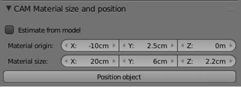
A work piece location (displacement from the center of coordinates) should be set in the fieldss Material origin.
Displacement of a work piece along the X axis is set -10 cm in this example in order to compensate a mismatch between centers of coordinates in BlenderCAM and SkyOne.
Displacement of a work piece along the Y axis is set 2.5 cm in this example for more convinient placement and fixing of a work piece on the table.
Position of a model should be set in the section Location on the N-panel.
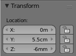
Displacement of the model along Z axis (equal to the model's height) is set for full cutting of the model from the work piece. So the top edge of the model is aligned with top surface of the work piece. Displacement of the model along Y axis is necessary for correct placement of the model inside the work piece.
Upon the given settings the milling operation will be executed in the center of the printer's table at the middle of the work piece.
Tool path calculation and saving of a ready G-code
All settings can be saved for all following runnings of BlenderCAM. Press Ctrl+u buttons and confirm the warning "Save Startup file".
To calculate the tool path press the button "Calculate path" in the section "CAM operations". If "Auto export" option os checked, an output g-code file will be generated automatically.
Path calculation time depends on insert settings, 3D model and PC processor. It could tale a long time for complicated models and slow computers.
After the tool path is calculated, BlenderCAM creates a new object, which contains curves of tool movements. This object is used for G-code files generation. This object becomes selected and it is possible to rotate, scale or change it as any other objects in BlenderCAM.
To export the tool path into g-code, press the button "Export gcode".
If the program reports an error (concerned to location, paths or not exsisting objects), save the model with all settings into file .blend (menu File > Save as), then close the program, then re-open it again and load the saved .blend file (menu File > Open or File > Open Recent).
Approximate time of the operation is displayed in the section "CAM info & warnings" after successfull path calculation (155 min for this example). A warning "Operation exceeds your machine limits" also will be displayed in this section.
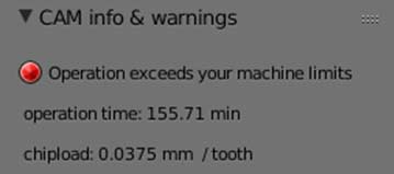
This warning is caused by the work piece and model displacement outward the machine limits, which were done to compensate mismatching of X-axis centers of coordinates of BlenderCAM and SkyOne. Please, control that the model is inside the machine's work zone by youself.
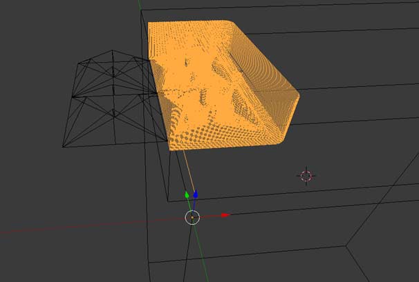
Possible path calculation errors
- Only a half of the model is used for tool path calculation - the second half of the model is located outwards the material (work piece):
- Incorrcet model placing along Z-axis. G-code contains only free movements of the tool above the work piece:
- Incorrect settings of tool properties (too thick tool is selected):
See also: