Engraving and milling of soft materials using 3D printer SkyOne
Apart from the primary function - printing of 3D models, 3D printer SkyOne has additional features - it is a light CNC milling machine. We offer special engraving and milling set for implementation of these functions.
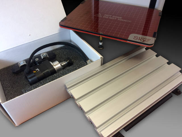
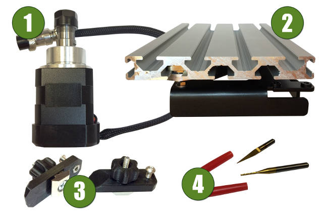
Complete equipment
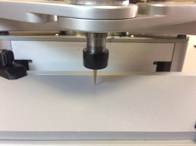
- Spindle. It is based on a BLDC motor 53 W. Rotor speed is 4000 rpm. Tool clamping - collet chuck attachment ER11. В
- Workholding table. It is made from aluminium section. Table dimensions are 190 x 120 mm. T-shaped sockets (8 mm) are used for workpiece positioning .
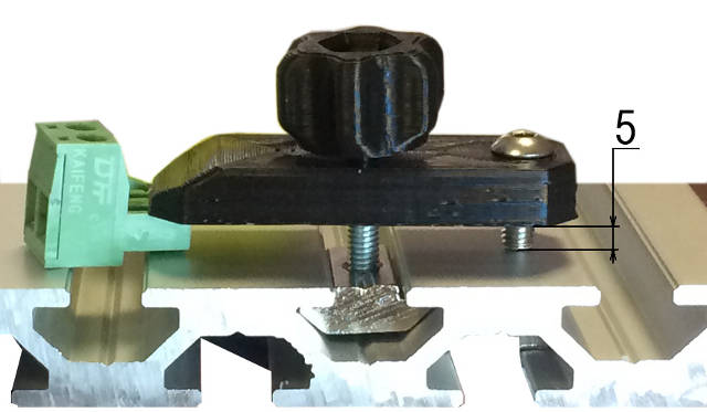
- Clamping fixtures. Two plastic hold-down tools - to fasten an in-process part to the table using T-shaped sockets. Clamping plates, thumb-screws and adjusting screws are included.
- Milling cutters. Two milling cutters are included - coned and cylindrical.
Preparation for engraving
As a first step it is needed to choose what we will pattern - a picture, and what we will pattern on - a surface. The surface for engraving should be plate, the object thickness no more than 5 mm. Otherwise we will need other fixing screws. And if the thickness goes beyond 10 mm, we will need other clamping fixtures.
One more important notice - the detail flat should be parallel to the table flat. Otherwise engraving depth will fluctuate.
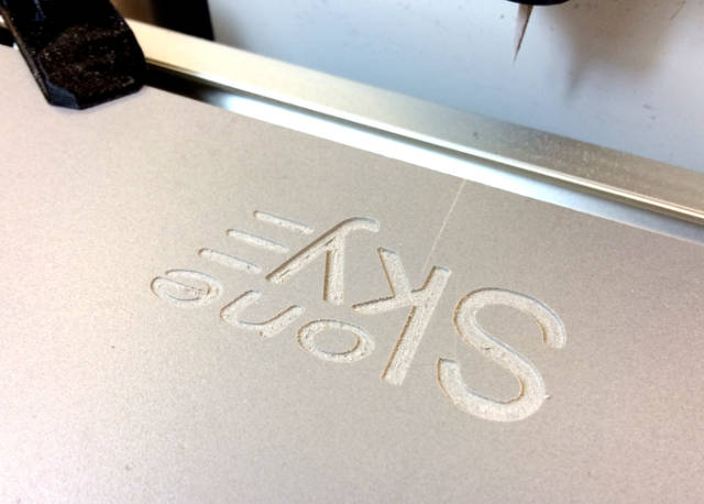
As an example we choose a plate made from foamed plastic and logotype "SkyOne" as a picture to pattern.
The engraving will be done with use of the printing software Repetier-Host. As this application works fine with G-codes, we will use it and we should convert a pixel image into commands, which are suitable for the printer (G-codes).
To covert a pixel image into G-codes there are specific programs, such as: SolidCAM, ArtCAM or free browser program jscut.org. It could be downloaded and used off-line.
JSCIT works just with files with *.SVG extension. So we should convert the pixel image to svg.
We use free software Inkscape to edit the pixel image. It is available for downloading from the official web site inkscape.org for few OS: Linux, Windows and MacOS X.
Image editing
Use file import (File > Import) to add the image to a workspace of the prigram. All bit map import settings we leave unchanged. Aftre that press a right mouse button on the imported image and select a command "Trace Bitmap..." . Tracing settings should be chosed in-situ and depend on saturation of the original image. As we use black-and-white image in our exampe, all settings are left unchanged.
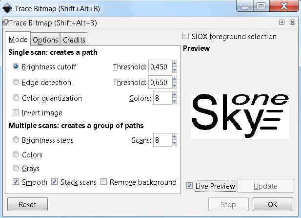
Press the button "Ok" and just close the tracing window after processing. Now we need just a vector drawing, it has more distinct limits compared to the original image. Save the vector drawing with .svg extention.
Now open web site jscut.org and press the button "Launch!".
Select "Open SVG" on the tool palette and upload the prepared vector file by selecting the menu "Local".
Click left mouse button at the image so as it became selected and turned to blue color. Now engraving settings should be done.
JSCUT settings
- Resolution - pixels number per inch - leave unaltered – 96 px pre inch, as the image was prepared in inkscape.
- Tabs – we will not use.
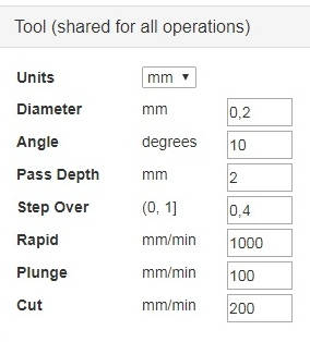
- Tool – parameters of the cutting tool.
- Units (measurement system) – we will use the metric system – mm.
- Diameter (diameter of the tool cutting part) – we will use a coned cutter, so the minimum diameter 0.2 mm should be set.
- Angle (grinding angle of the cutting tool) – 10 degrees.
- Pass Depth (depth-of-cut) – Z-axis feeding depth. Use minimum value of this parameter if process hard material or if higher quality of processing is needed. As we use soft material, we will set the value of this parameter 2 mm.
- Step Over (offset value for the next cut) - the less this value - the more time for processing is needed. we set 0.4 mm.
- Rapid (No-load tool feed speed) - 1000 mm/min
- Plunge (Z-axis tool feed speed, during cutting) – 100 mm/min
- Cut – (tool feed speed, during cutting) 200 mm/min
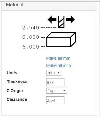
- Material – parameters of the work material
- Units (measurement system) – we will use the metric system – mm.
- Thickness (thickness of the material) – 6 mm.
- Z Origin (Z-axis zero position) – Top (upper side of the material)
- Clearance (clearance height of the cutting tool above the position Z Origin) – 2.54 mm.
- Curve To Line Conversion (parameters of converting a curve into a straight line)
- Minimum segments (minimum number of line segments for curve converting) – 1
- Minimum segments Length, mm – 0.254 mm
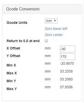
- Gcode Conversions (parameters of G-codes conversion). Coordinates of position of a working place (engraving area) - x and y axises. Determined on a trial basis, offset parameters for engraving of the image at the center of the table are the next: X offset -90 mm and Y offset 170 mm.
After all settings are adjusted, press the button "Create Operation". The dropdown menu of processing methods selection (Pocket, Inside, Outside, Engrave and V Pocket) and depth-of-cut input box ("Deep") will appear in the section "Operations".
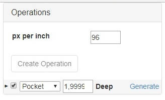
To generate G-codes press the button "Generate" and wait.
Processing methods
- Pocket – cutting of a contour and fill (the whole figure)
- Inside – cutting just a contour. The edge of the milling cutter doesn't go beyond the image contour.
- Outside – cutting just a contour. The edge of the milling cutter goes beyond the image contour. The image size is increased by the value of the cutter diameter.
- Engrave – cutting just a contour. The cutter center goes on the contour line.
- V Pocket – cutting of a contour with varied depth - minimum at corners and maximum at middle of sections. It is applicable just for cutters with cone cutters.
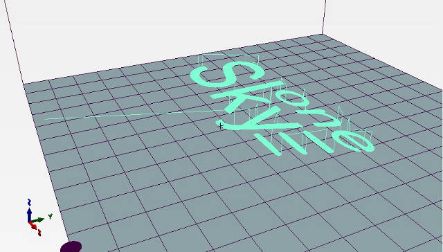
Open the tab "Simulate GCODE" to see the approximate result. For our example it should be like the image below:

Save the result GCode to the local drive and then open this file in the 3D printing application - Repetier-Host.
Printer settings
IMPORTANT! Because of the difference in thickness of the table for 3D printing and table for engraving, thickness of the processing material and size of cutting tool (length), it is necessary to set the new value of Z-axis zero position before starting the work.
- Turn on the printer. Make a connection in Repetier Host.
- Upload generated G-codes file.
- Open the tab "Control". Please ensure, that nothing hinders the spindel rotation and the cutter movement!
- Start the motor of the cutter – press the button of the extruder turning on. Turn the temperature to the maximum value.
- Move the table with the detail to a safe distance - to prevent impact of the table and cutter. In order to do that insert the command G1 Z50 into the box of G-CODE. If the detail thickness is more than 6-10 mm, the value on the Z-axis should be higher.
- Move the tool toward over 30-40 mm along Y axis, so as the center of the cutter would be placed above the procesing surface of the detail. (Commands G1 Y40).
- Start to lift the table little by little, until the end of the cutter (it should rotate at this moment) comes close to the surface. One by one input commands for decreasing distance along Z axis: G1 Z39, G1 Z38 etc. Keep having a control over the position of the cutter end.
- As the cutter end nearly toches the surface, assign the zero postion value of the Z axis. Input command G92 Z0 (set zero position of the Z axis).
- Launch the printing and wait the result.
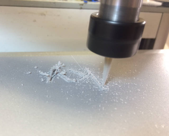
Machining process:
Final result: